The End Of The Zig – Organizing Motorhome 12v Wiring
Before I start I want to point out that I am not a professional electrician, but my mind does seem to work in a schematic (if not scatterbrain!) basis. So please read this as a “how I did” post rather than a “how to” post.
Our motorhome came fitted with a ZIG Marque I power unit. Zig units have a built in battery voltmeter and a 2-way rocker power switch. This allows you select the leisure battery to supply power to the motorhome habitation area by putting the switch down.
If your leisure battery goes flat and you have an emergency power need in the habitation area, you can flick the switch upwards to draw power from the starter battery. Obvious care needs to be exercised in this mode to make sure you don’t render your vehicle immobile.

As our motorhome is built on a lorry chassis, the starter battery system is 24 volts and unsuitable for the habitation area, so was not connected to the zig unit rendering this function redundant. However on the flip side, I know my starter batteries are safe from being depleted.
As well as the dual power switch and the voltmeter, the zig unit has 3 fused outlet switches. When I inspected the wiring layout in the van, I decided that 3 switches were inadequate as there were already a couple of circuits piggy-backed off each switch. I wanted to get a unit with more switches so I could separate out each of the circuits on to individual switches.
The first job was to disconnect the wiring from the back of the existing zig unit. Whilst these are just spade fittings it wasn’t just as simple as removing them.
Why do electricians never label wires?? Before each wire was removed I had to discover which circuit that power lead was responsible for. As I discovered which each power lead operated in the van, I labelled the cable as to its function.
There were 3 additional circuits which were not connected to the zig, which had constant power. These were the switch for the step lights, a second one for the outside light and a third supplied the 12 volt power to the rear bedroom.
These feeds were taken from a constant power supply and then protected through a fuse block. I had added a fourth circuit to this fuse block to power new 12 volt and USB sockets that I was fitting around the van.
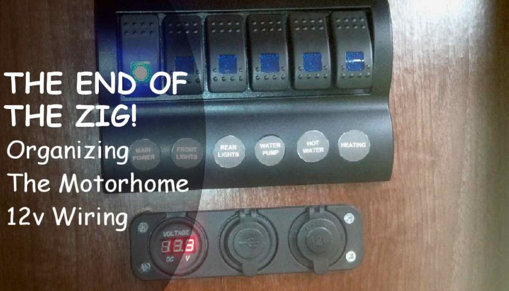
Once all the circuits were identified and separated, I had to find a replacement power distribution panel which would have the 6 switches I required. ZIG units of this size fetch crazy prices, so I came across a marine switch panel on Amazon, with the 6 illuminated switches all pre-wired and complete with protective trips.
As campervans share many of the same building characteristics as boats, this marine switch panel would be ideal for my needs.

The only problem was that it did not have a volt meter on the panel. Luckily, I had previously purchased a second panel which consisted of a volt meter, a 12 volt outlet and a double USB outlet which I planned to use for charging mobile phones, tablets etc. It also meant there would be a 12v socket close to the main door which would be useful for using a compressor to inflate the tyres.

I also set about modifying the pre-wiring of the marine switch panel. The power input was to connect to the bottom left hand spade. This would automatically provide power to all 6 switches using the loop connectors along the bottom. This power would then move up through trip breakers to each switch.
I wanted the first switch when powered on to operate the subsidiary panel to allow me to see the voltage display etc, and then feed down to power the remaining switches. This means that when I flick off the main switch – all power to the habitation area can be isolated in one simple action.

You may be able to see on the back of the panel my modified wiring. Power still comes into the panel at the original point, but now only travels up through the initial breaker to the main switch. When this switch is closed, 2 leads leave the top of the switch. One powers the subsidiary panel and the second one feeds power to the remaining switches.
With the zig unit now removed, I needed to measure the 2 new panels for size and see how they would fit. I drew out an accurate template using MS Publisher and printed out the template sheet. I could then attach this to the wall where the zig unit was originally fitted and see what cutting needed to be done. For the subsidiary panel, the back of each of the units was round, so I planned to use a 38mm hole saw to cut out the 3 main areas, then cut between the holes to allow access for the wiring.


I didn’t want to damage the wood surface with the base of a jigsaw, so decided to cut out the remaining wood using a small hand drywall saw. This took a bit more effort but I had the piece removed in around 5 minutes. Unfortunately I had drawn the template too neat and had to go back and trim around the holes to allow a little wiggle room to fit the switch panel.
Once both panels had a dry fit, they could be screwed into place and the cover of the top panel fitted.


For the wiring, I connected the main positive and negative feeds to the top panel. The second positive out from the main power switch went to the sub panel as did a further negative feed.
I then took a wire from the top of each main switch and connected each of them to a spade fuse block holder. The feed lines I had earlier labelled then exited the fuse block to their various devices. I know that the main switch panel is fitted with trip protectors – but the fuse box will provide an additional second layer of protection.


I also fitted a 30 amp breaker switch to the main power lead coming from the battery. This will also allow me to break the circuit and cut all power to the habitation area – including the constantly powered items from the bottom fuse box which are not controlled from the main switch panel.
Finally it was a matter of tying all the cables together to tidy up the wiring as much as possible.
I am now much happier with the overall wiring of the van. I have a master cut-off breaker/switch. Each circuit is on its own switch and/or fuse and finally all the cables are labelled. This will make things much easier to diagnose if there are any future wiring problems.
Next major electrical job is to tackle the installation of the solar panel and replacement of the 2 leisure batteries.
Let me know what you think and if you have found any of this information helpful.