New Leisure Batteries and Wiring Tidy Up
NEW LEISURE BATTERIES AND BATTERY LOCKER WIRING TIDY UP
I mentioned in my earlier post on how to select a solar panel that I was going to change the leisure batteries to new larger capacity units. I was restricted by space in the battery locker as to the maximum dimension batteries I could install, so with dimensions in hand I hit the internet to track down replacements. Batteries available locally were a horrendous price, but we also have to weigh up the cost of delivery to Northern Ireland and also the fact that many suppliers will not even send to here.
Numerous searching and comparing led me to Tayna batteries. They have a huge range of batteries in stock for all possible uses. I was able to select two 110Ah dual post batteries within our size limits. I have to say that dealing with Tayna was very easy. I ordered the batteries late on a Thursday night. Shipping to NI was a bit more expensive than the UK mainland, but still very reasonable. They would have received the order on Friday and the batteries were packed and shipped out the same day. They were on our doorstep on Monday morning. Nice one Tayna. If you are needing a new battery, give them a try at www.tayna.co.uk.
![]()
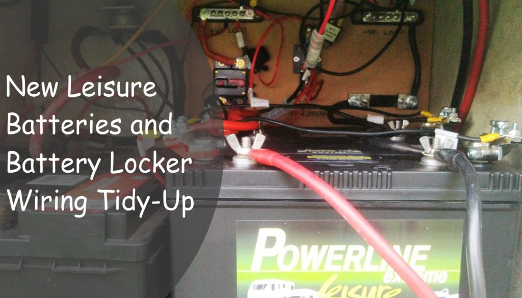
The reason for dual post batteries will soon become evident. This was the old battery set up with every imaginable cable connected directly to the batteries resembling a famous junction on the M6 near Birmingham.


The first task is to connect the 2 batteries together. They are connected in parallel (positive to positive and negative to negative). This creates a power bank with the same voltage (12v) but doubles up the storage capacity to 220Ah. In contrast the lorry starter batteries are connected in series (positive to negative) which keeps the storage capacity the same but doubles up the supply voltage to 24v, which is required for the heavy duty starter motor and cab electrics.
I had ordered up some battery connecting cable and copper tube ring connectors to make up the connection cables. The copper tube terminals come in a variety of bore sizes to match the cable you are using and a variety of ring sizes to match the connection bolts. In my case I had ordered 16mm cable which is rated to 110 amps, so matched this up with 16mm copper tube connectors in 6mm, 8mm, and 10mm ring sizes to match the various connections I had to make.
Having measured the length of cables needed, I found the easiest way to cut through the thick cable was to use an old pair of garden secateurs which cut through the cable easily. Once cut, strip off the insulating cable wall to expose just enough of the stranded copper to fit inside the copper tube terminals and twist the copper strands tightly together by hand.


There are a number of ways to connect the copper tube terminals to the cable. They can be soldered into the connector, secured with a metal punch or crimped on using a special crimping tool. Although I didn’t have the special tool, I decided to crimp on the cables using an alternative, simple and more secure method. Having slipped the exposed copper strands inside the tube connection, I mounted it in a large table vice, and slowly tightened the vice as much as I could. This produced a very tight crimped connection and even left a diamond shaped pattern on the connector and there was no way they were ever coming apart. I then covered each connection with heat shrink tubing to produce a neatly finished cable.


It was time for a make-over, tidy and update of the battery wiring system so a plan was hatched to put together a distribution board with a few new additions.
![]()
The distribution board is made up of a number of elements. To keep the number of connections to the battery terminals to a minimum, I have added a positive and negative bus bar for the various van feeds. This leaves the only cables connected directly to the batteries as the main feed to the distribution board and the charging supplies.
I was originally connecting the inverter directly to the battery, but I have also now moved these to the bus bar for reasons I will set out later. Here is the wiring diagram except that the inverter connections have moved to the bus bar.
![]()
A main feed cable leaves the battery and is connected through a 100 Amp breaker fuse to the positive bus bar. The breaker fuse protects the circuit and also allows me to disconnect all power to the habitation area by the simple flick of the switch. Fuses should always be matched to the cable rating used to prevent the cable from overheating. In my case I was using 16mm feed cable which is rated at 110 Amps, so the 100 Amp breaker fuse is a good match.
The return negative feeds are all attached to the negative bus bar. From here there is a connecting cable to one side of a shunt, the other side of the shunt is connected to the battery negative terminal. The negative terminal is then earthed to the main van earthing point.
The shunt is a method of measuring the current used through the supply and will be connected to a meter which will measure amps being used at any time, total amps used over a period of time and remaining storage capacity of the batteries. I will write about this later once I have the meter connected up and running. This is the reason I have moved the supply leads to the inverter from the battery to the bus bar as it will also measure any current used by the inverter.
The final element to the distribution board is a 20 Amp breaker fuse for the charging supply from the solar panel. Again this matches the rating of the 4mm cable used, and also allows me to easily isolate the charge from the solar panel to the battery.
The battery locker is made from fibreglass, so I attached the distribution board to the back of the battery locker using Sikaflex 512. Now it was just a matter of following the wiring diagram and connecting everything together.

I now have a tidier, much easier to follow wiring scheme as well as double the capacity storage in the batteries. In conjunction with the solar panel, this should keep the need to connect to mains to a minimum. Here is a picture of the final result.

Let me know what you think in the comments below and if I have made any glaring mistakes, feel free to point them out as I am keen to learn. Up to now everything is working perfectly 
I am not a professional electrician so this article is for information only. Whilst it may help if you propose to take on a similar task, if you decide to change the wiring in your own van you should do your own research, or consult a professional.
October 18, 2016 @ 5:19 pm
Craig loves the article and you two would get along so well. Everything has to have its place and be neat and tidy! He’s scouted your site a few times and its left him with a few ideas and tweaks, so thanks for sharing.
Just so you know, I’ve actually gone to leave comments a few times but thought comments were switched off. I assumed your bio and the share icons were the end of the post but now I know!
October 18, 2016 @ 8:01 pm
Thanks for popping by Joanne. You seem to be enjoying Greece. I would have loved to visit there this winter but by the time we leave I think it will be too long a trek.
I think Craig needs to buy an older vehicle – something to get his teeth into and keep him occupied
November 11, 2020 @ 6:31 am
Hi, I’m undertaking a similar project, thanks for the blog entry. I am curious, why not connect the solar and charger on the loads side of the shunt so you get an appreciation of current in and out?
November 12, 2020 @ 2:57 pm
Hi, I never got around to using the shunt or wiring up the meter! Our power supply was always adequate during winter in Spain & Portugal.